


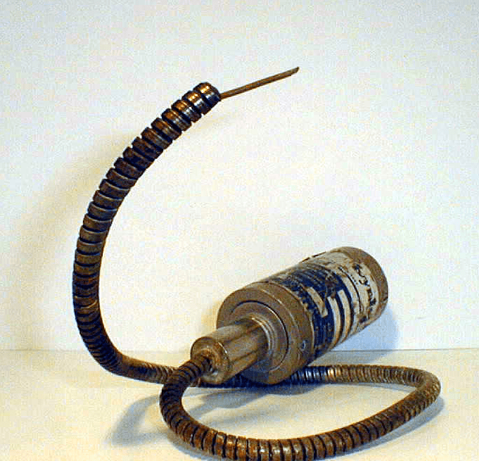
Damage to a pressure transducer is commonly caused by their installation into an improperly machined hole. In forcing a transducer into a too-small or eccentric hole, the transducer diaphragm may be crushed and as a result the instrument will not function.
Causes of Transducer Field Returns & Solutions
David Azevedo, Global Technical Support Manager
07.16.2018
The Transducer Must Be Mounted Correctly:
Damage to a pressure transducer is commonly caused by their installation into an improperly machined hole. In forcing a transducer into a too-small or eccentric hole, the transducer diaphragm may be crushed and as a result the instrument will not function.
Tool kits available for machining the mounting hole will help to make sure the holes are properly sized. A mounting torque of 100 to 200 inch pounds (for ½-20 UNF) is essential to form an adequate seal; however, excessive mounting torque will cause seizing. To prevent problems with seizing, a high temperature anti-seize compound should be applied to the transducer threads prior to installation. Transducers installed at a mounting torque above 500 inch pounds will be difficult to remove even when anti-seize compound is applied.
Ensure That the Mounting Hole Thread Size is Correct:
The abrasion from screwing a transducer into a mounting hole with an incorrect thread size will damage the instrument’s threads. This damage may prevent a good tight seal, resulting in material leakage, and the instrument will not function properly or safely. The proper dimensions for the mounting hole must be used to avoid thread galling. (The threads are, generally the industry standard of ½ - 20 UNF 2B.) A mounting well gage plug should be used to verify that the mounting hole is correctly machined and cleaned.
The Mounting Holes Must Be Clean:
It is important that the transducer mounting holes are kept clean and free of any plastic buildup. Before an extruder is cleaned all of the transducers should be removed from the barrel to avoid their being damaged. When they are removed, plastic is likely to flow into the mounting holes and harden. If this hard plastic residue is not removed extensive tip damage will result when the transducers are re-inserted. A cleaning tool kit can be used to remove the contaminant plastic. It should be noted that repeated cleaning may produce “too deep” holes and result in damage to the transducer tip. If this is seen, spacers should be used to raise the transducer.
Select a Good Location:
Transducers may be located in the barrel, before a screen changer, before and after a melt pump, or in the die. When a transducer is positioned too far upstream in the barrel, un-melted plastic pellets may abrade against the transducer tip, resulting in damage. If a transducer is positioned too far back in the mounting hole, a stagnant pool of melted plastic will build up between the transducer tip and the screw flights. Over time this plastic will degrade to carbon, which will prevent the transmission of an accurate pressure signal. On the other hand, if the transducer extends too far into the barrel the screw flights can shear off the unit’s sensor tip.
Clean the Transducer with Care:
All of the transducers should be removed before cleaning an extruder barrel with either a wire brush or special cleaning compounds. Either one of these can ruin the transducer diaphragm. The transducer should be removed while the barrel is hot and tip wiped clean with a non-abrasive cloth. The transducer hole should be cleaned at this time with a cleaning drill/guide sleeve.
Avoid Cold Starts:
Both the transducer and extruder can be damaged if the extruder is not brought up to operating temperature before the machinery begins operating. A sufficient “soak time” must be provided for the plastic to go from it’s solid to molten state. In addition, it should be noted that if a transducer is removed from a cold extruder, material might adhere to the transducer tip causing the diaphragm to tear off the unit. Make sure the barrel is warm enough, that any plastic present will be soft, before removing the transducer.
Don’t Overpressure the Transducer:
Even though transducers are designed to withstand 1.5 times overpressure, avoid the risk of applying too much pressure by making sure that you are using the correct model designed for your range of extrusion operation pressures. A good rule of thumb is to use transducers that are built to withstand twice the rated pressure in your process. Then the extruder will have to be operating at an extremely high (and unsafe) pressure level for the transducer to fail.
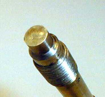
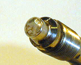
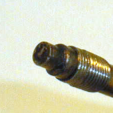
Diaphragm damaged by a sharp edge
Causes:
- Damage through sharp edge contact (screwdriver or knife)
- Dropped
- Contact with degraded polymer in hole
Solutions:
- Use protective cap (transport, storage)
- Check hole with gauge plug for burrs or hardened plastic
- Clean hole with Dynisco cleaning tool
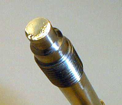
Diaphragm ground off
Causes:
- Contact with abrasive material in process
- Cleaning with wire brush or wheel
Solutions:
- Dymax coating for abrasive applications
- Wipe tip while hot with cloth to remove plastic
- Never use wire brush or cleaning wheel
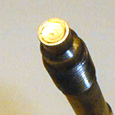
Diaphragm torn
Causes:
- Removal when the material was in a cold or hardened state - Shrinkage of adhesive materials
- Sensor located over flite (fatigue)
Solutions:
- Remove while hot to avoid adhesion
- Double-strength Diaphragm (T80) or TiN coated diaphragm
- Relocate sensor
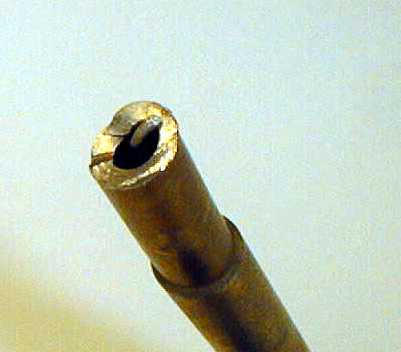
Diaphragm is missing
Causes:
- Removal in cold material condition
- Shrinkage of adhesive materials
- Diaphragm bonded to the material
Solutions:
- Remove while hot to avoid adhesion
- Double-strength Diaphragm (T80) or TiN coated diaphragm
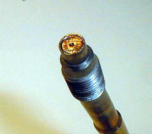
Diaphragm is wavy; the edge is crushed on the sensor tip
Causes:
- High shear tension
- Lateral crushing when installing (cross thread)
- Non-concentric mounting hole
Solutions:
- Check the install location
- Double strength Diaphragm (option T80)
- Check hole with gauge plug for burrs or hardened plastic
- Clean hole with Dynisco cleaning tool
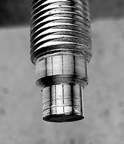
Seal surface is damaged
Causes:
- Poor mounting hole or cross-threading
Solutions:
- Check hole with gauge plug for burrs or hardened plastic
- Verify threads with gage plug
- Clean hole with Dynisco cleaning tool
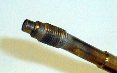
Shaft bent
Causes:
- External mechanical effect on stem
Solutions:
- Stem is too long – shorten stem to match depth
- Over-torqued
Shaft torn off
Causes:
- Mechanical effect
- Thread has been fused in the hole (galled)
Solutions:
- Apply Anti-seize to thread prior to installation
- Follow torque requirements
- Use Hastalloy threads to minimize galling
Flexible connection (capillary) broken
Causes:
- Bend radius too tight
- Installation damage
- Capillary cut or stretched to capacity
Solutions:
- Handle carefully, due to exposed capillary
- Lengthen flex or use 435XL version
Thread damaged
Causes:
- Poor mounting hole
- Forced insertion/removal
Solutions:
- Check hole with gauge plug for burrs or hardened plastic
- Clean hole with Dynisco cleaning tool