Presented by: David Azevedo / Global Support Manager
Pressure Sensor Care & Maintenance
Presented by: David Azevedo / Global Support Manager
Question: What is the definition of a transducer?
Answer: A transducer is a device that converts one type of energy to another. The conversion can be to/from electrical, electro-mechanical, electromagnetic, photonic, photovoltaic, or any other form of energy.
Example: A Guitar amplifier, which takes vibrations from the strings of the guitar, and converts to an sound frequency we can hear through the speaker via electromagnetic conversion.
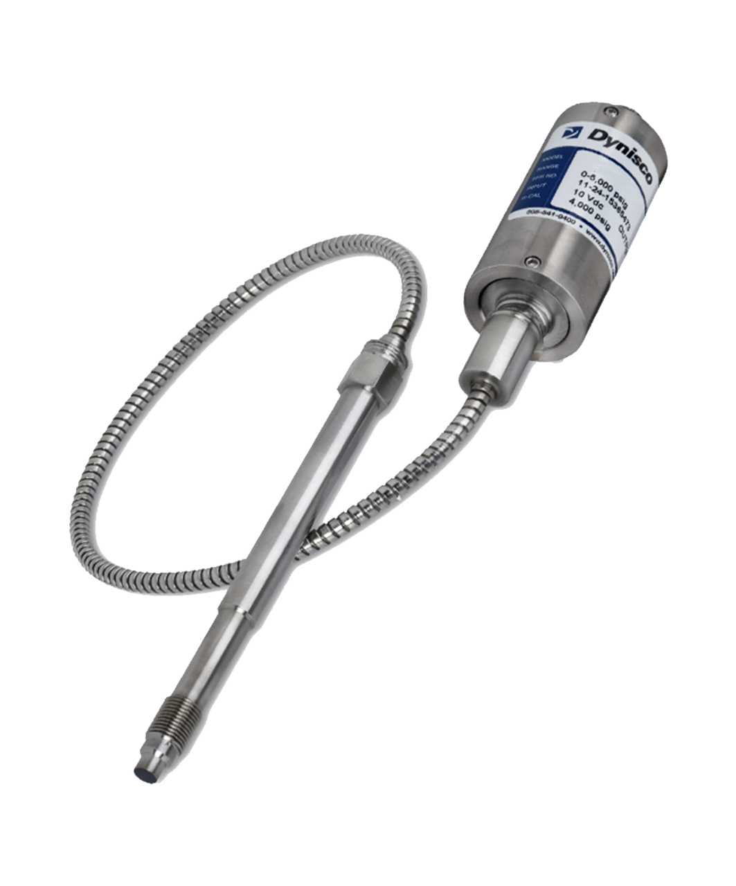
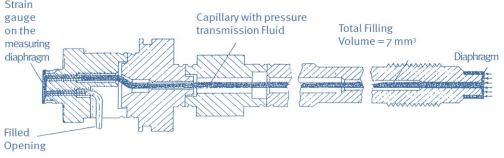
Question: How does a pressure transducer work?
Answer: By incorporating the foil strain gauge, a filled capillary and diaphragms to obtain a controlled pressure change which is converted electronically to signal output, that is scaled to a specific pressure range.
Available signal outputs for Dynisco sensors:
Millivolt (one thousandth of a volt) symbol = mV
Volt (the measure of electric potential) symbol = V
Milliamps (one thousandth of an ampere) symbol= mA
Available ranges for the various signal outputs:
Millivolt= 2mV/V, 3mV/V, 3.33mV/V (other ranges available upon request)
Volt= 0-5V, 1-6V, 0-10V, 1-11V (other ranges available upon request)
Milliamps= 4-20mA, 4-20mA with HART (pressure ranges can be assigned)
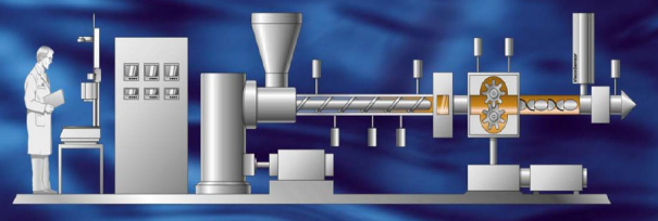
In Plastic Extrusion, pressure variation at the die entrance, could be caused be either an actual variation in rate from the extruder, or variation in temperature affecting viscosity.
Pressure fluctuations are typically controlled with gear pumps
Gear pumps can be manufactured to have pressure transducer ports
Transducers will help the operator make changes to process variables based on pressure readings captured via signal output to instrumentation.
Instrumentation can be programmed to stop the Extruder if a pressure condition exists that will compromise the equipment.
Pressure signals to instrumentation enable control of screen changers that filter out particle contaminates in the melt.
Instruments will monitor and log pressure variations at the die head, providing the operator with data to improve process
When Melt Temperature is stable, pressure variations are often caused by:
Variations in Feed Stock
Inconsistent screw speed
Barrel Temperature change
Poor screw design
Dynisco pressure transducers and Instruments enable detection of these conditions
 |
 |
|---|
|
Increased productivity Quality products Reduced waste Reduced costs Less Down Time Increased Profits |
Happier customers Longer life Safety Safety Safety Safety |
|---|
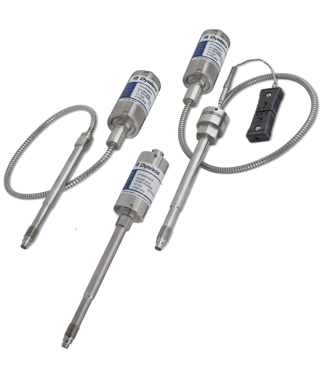
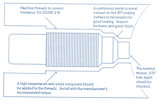
• Dynisco’s innovative cap diaphragm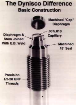
• Machined 45 degree sealing surface
• Industry standard ½-20 threads
• One-piece stem construction (most models)
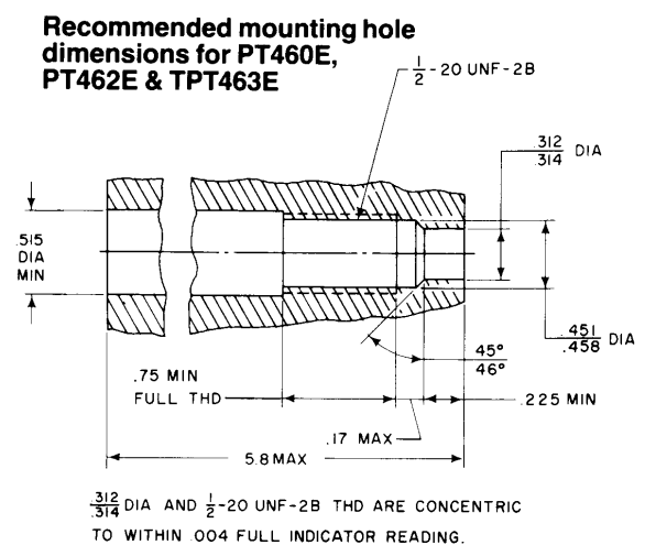
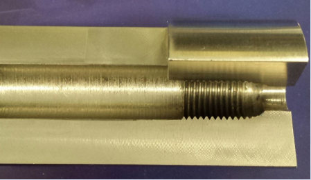
• The threads are the industry standard of 1/2-20 UNF
• Improper dimensions will cause thread galling and material leakage
• Insure proper hole dimensions with Gauge Plug included in the Dynisco Cleaning Tool Kit, part number 200100
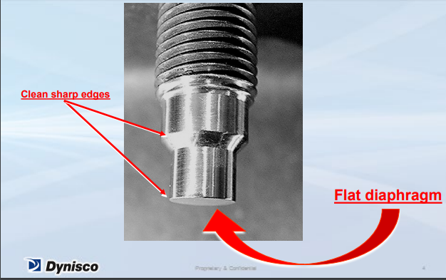
This is the way a transducer tip should look when it’s new.
Before screen changer
Before melt pump
After melt pump
In the diesVariations in Feed Stock
Prevents pressure build up
Insures adequate melt feed to pump
Insures adequate pump pressure to die
Insures adequate pressure for product
----------INSURES SAFETY--------------
Too close to the feed zone can cause damage from unplasticized pellets
Mounting too shallow in the hole can cause material degradation and freeze-off
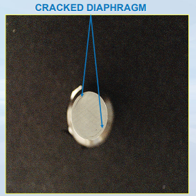
Mounting too deep can cause tip damage and measurement errors
Repeated hole cleaning can cause “too deep” holes, and possible tip damage. ( use spacers )
Standard transducers are NOT water tight!!!!
Dynisco circuitry can handle extrusion plant environments, but will not operate when wet
Specify water tight transducers when wet operation is unavoidable
Mounting holes are important ! ! !
They cannot be eccentric
They cannot be too small
They cannot be too large
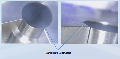
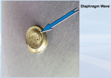
How deep should transducer be?
Typically recessed around 0.010”
This depth will prevent any unnecessary diaphragm wear and help prolong the life of the pressure transducer
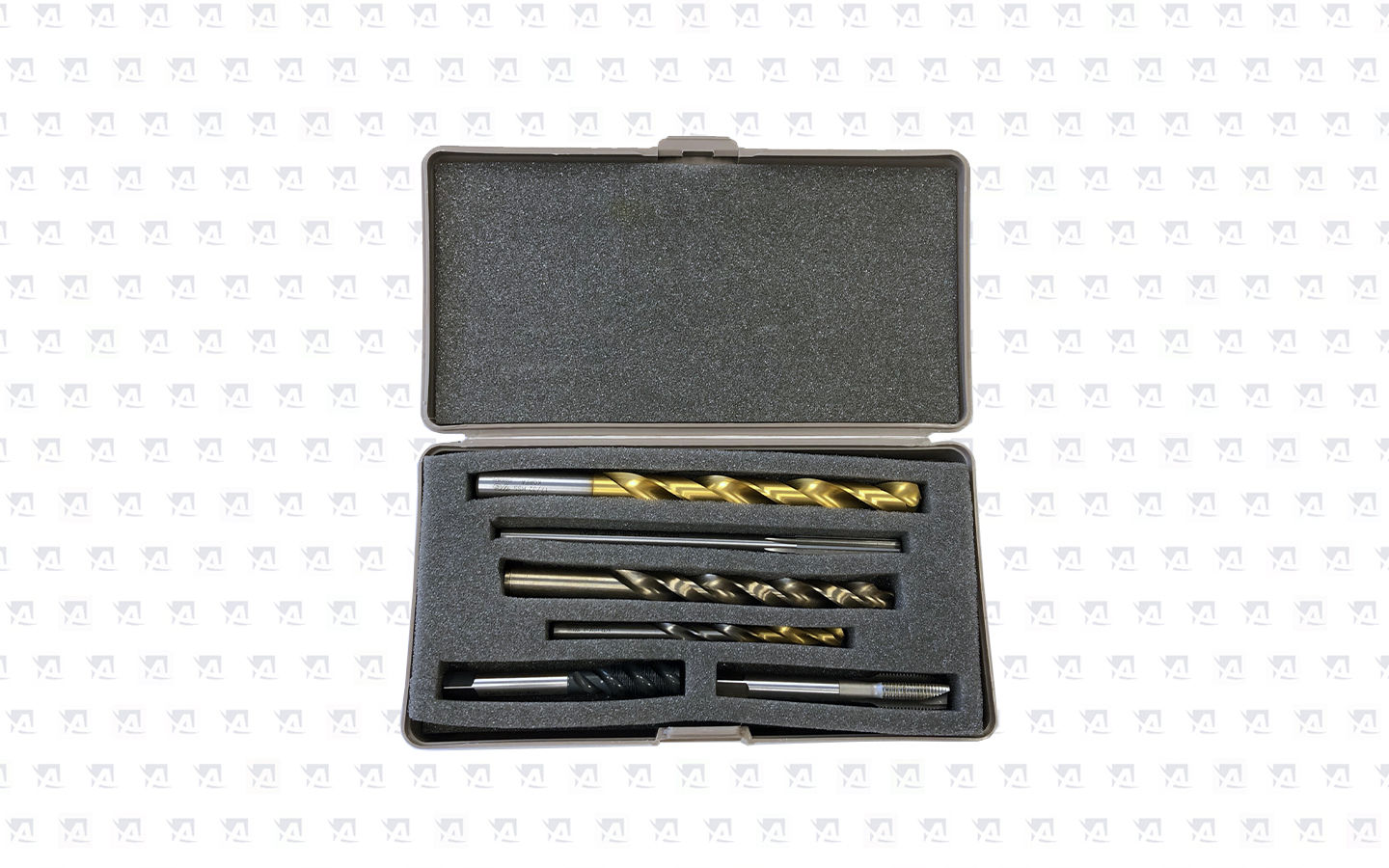
Kit # to make holes…PN 200925
If hole is already too deep, use stackable 45 degree 0.025” copper spacers (PN 633511)
Aluminum also available

Always use a high temperature anti-seize compound when mounting transducers
Always use proper mounting torque
100-200 inch-pounds (8-16 ft lbs) may very on transducer type
500 inch-pounds MAXIMUM (250 for push rod)
RULE OF THUMB…finger tight plus 1/4 turnVariations in Feed Stock
To machine a new hole use Dynisco’s Machining Tool Kit, # 200925
Use proper mounting torque upon installation:
Proper Torque
See Product Manual
Less causes leaking
More causes seizing and damage to the transducer
IMG
ALWAYS remove the transducer before cleaning the barrel with abrasives, cleaning compounds or a wire brush
Remove the transducer with the barrel HOT and wipe the transducer tip clean
Remember to go back and clean the hole with the cleaning drill/guide sleeve
Dynisco cleaning tool kit (p/n 200100) will make the job easy
Remove the transducers when cleaning the barrel
Remove them when they’re HOT
Remove any plastic buildup in the hole
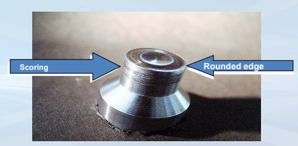
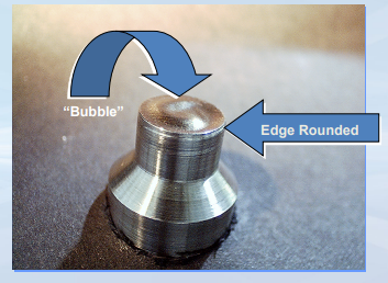
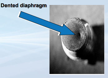
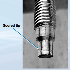
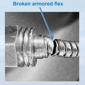
Problem
– Damaged tip
– No response
– Galled threads
Reason
– Improper hole
– Over-pressured
– No anti-seize used

Transducers operate best at midrange.
Transducers can withstand 1.5 times overpressure without damage.
Overpressure can occur when cold material slows the flow.
Verify that your transducer will be operating within their rated range
Pay special attention to the pressure range when extruding different materials
Like people, over-pressured transducers cannot perform their job properly
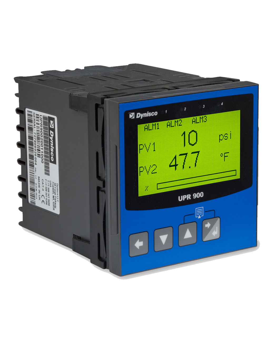
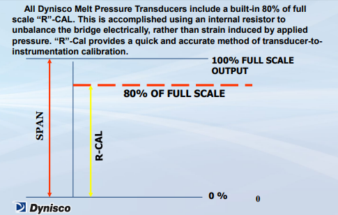
• When? ------—When it’s up to operating temperature and at zero pressure.
How often?--------When your ISO9000 standards dictate, or if the zero appears to have shifted.
It’s easy! --------Dynisco transducers have a built in 80% R-Cal, and our indicators use this R-Cal to calibrate the span.
Stabilize your process
Operate more efficiently
Increase profit
Increase consistency and quality
Help your profitability
Dynisco manufactures for the extrusion industry the most rugged and reliable transducers
Dynisco is an ISO9001 company
Proper care and handling will provide you with many years of service